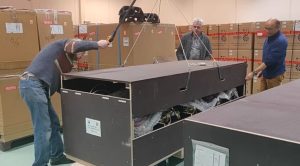
17 January 2025 – Today we start a series of items highlighting the work of our technical staff in the labs of KM3NeT. Numerous technicians and engineers are working on the construction of the ARCA and ORCA detectors of the KM3NeT neutrino telescope. Together, but in distributed labs, they design and build the many detector components, assemble them into thousands of optical modules and integrate them into hundreds of deployment-ready detection units. It requires high standards of quality control and logistics between the labs.
Spotlights on the Nikhef lab
In this first item we set the spotlights on the KM3NeT production lab of the Nikhef institute in Amsterdam, The Netherlands. It is the lab where our multi-PMT optical module was born and it is one of the first production labs in KM3NeT.
Video’s in this item: Courtesy Nikhef – Marco Kraan. He has filmed the full process of assembling an optical module at Nikhef. Below we use his collection of short video clips.
“You just have to get the hang of it” according to Menno de Graaff, electronics engineer featuring in the clips.
The KM3NeT multi-PMT optical module is the key component of the neutrino telescope. It is a complex sensor module that registers the Cherenkov light from the charged particles from neutrino interactions with the seawater and monitors the position of the module in the deep sea. All sensors and the electronic boards for their power and readout are densely packed in a pressure resistant glass sphere. Therefore, assembly of the module requires highly skilled technicians.
Step 1 – The assembly of an optical module starts with the empty pressure resistant glass hemispheres.
Step 2 – In the top hemisphere an aluminum cooling ‘mushroom’ is glued to the glass using a gel, which is applied in layers to avoid bubble forming in the gel. Once in the deep sea the cooling mushroom will keep the temperature in the optical module below 30 degrees.
Step 3 – In the bottom hemisphere an acoustic sensor is glued to the glass using a hard adhesive for good contact with the glass. The sensor is part of the acoustic system used to monitor the position of the optical module in the deep sea.
Step 4 – Two electronic boards are installed in the cooling mushroom in the top hemisphere. One provides the electrical power to the sensors in the module. The other is the heart of the module – the central logic board that collects and digitises the signals of all sensors in the module and transmit the digitised data via optical fibres to the backbone cable of the detection unit that is connected to the electro-optical cable network toward the control station on the shore. The connection is made via a feedthrough in a hole in the glass hemisphere. It is carefully checked that the hole is leaktight after installation of the feedthrough.
Step 5 – On top of the central logic board a fibre tray is installed with the fibres that connect the board with the backbone cable of the detection unit.
Step 6 – Switch from the glass spheres to stacking the 31 photomultiplier tubes (PMTs). In the structure that later fills the top glass hemisphere, 12 PMTs are stacked leaving room for the cooling mushroom to pass. A reflective metal ring is put around each PMT to improve their light collection.
Step 7 – In the structure that later will be placed in the bottom glass hemisphere, 19 PMTs are stacked. Together the 31 PMTs form a ‘fly’s eye’ looking in almost all directions. The PMTs will ‘see’ the faint Cherenkov light of charged particles induced by neutrino interactions in the deep sea.
Step 8 – The structures filled with PMTs are placed in the prepared glass hemispheres and connected to the ‘octopus’ electronics boards which are placed in the space left between the PMTs. The hemispheres are ready for a functional test in the test room.
The two structures are connected through a test cable to verify the functional behaviour of the optical module before closing it. During the functional test, the PMTs, acoustic piezo sensor and a LED are verified to work according to specification. In addition, fibre and power connections are checked, as well as the temperature of the electronic boards.
Step 9 – Once the functional test is passed, the PMTs are fixed on their position in the glass sphere and the space between the PMTs and the glass is filled with a special highly transparent gel. This is necessary in order not to loose light during operation in the deep sea. The filling must be done with care to avoid forming of air bubbles in the gel. Air bubbles would distort the path of the light.
Step 10 – Time to close the two hemispheres. The trick is that the readout electronics boards of the PMTs in the lower hemisphere of the module must be mounted on the stem of the cooling ‘mushroom’ before closing the optical module. When everything is connected correctly, the module is closed and some air is removed from it to create a small underpression. Then the module is sealed with a sticky strip to prevent the two hemispheres getting loose during transportation or during deployment to the bottom of the Mediterranean Sea. Once in operation the two remain tightly close due to the high pressure in the deep sea. Finally, a collar for attachment to the supporting ropes of the detection unit is mounted.
Step 11 – The module is ready for connection to the electro-optical backbone cable of a detection unit. The backbone cable runs the full length of hundreds of metres along the detection unit. It comprises copper wires for electrical power and optical fibres for data transmission. The video clip presents a birds-eye view of two sets of the final product of 18 optical modules connected with a backbone cable.

Step 12 – The 18 optical modules connected to a backbone cable are shipped to the labs in France or Italy, which will build a ready-to-deploy detection unit and load it onto a launching vehicle for deployment in the deep sea.
This marks the end of our highlight of the work of technicians and engineers constructing KM3NeT multi-PMT optical modules and detection units at Nikhef.
In a next edition we will report on the work of technical staff in other KM3NeT labs.
Interested in the technical details of the KM3NeT multi-PMT optical module? We published a paper here.

